The short version
What the competition scores
A 45 cm turbine in a wind tunnel: power from 5 to 10 m/s, holding that power up to 13 m/s, stopping itself twice, and surviving. Any visible failure ends the test, so reliability beats aerodynamics.
What year one taught
We built a turbine in one semester, aborted our only practice run when the rotor shook, and did not pass tech inspection at the event. 6th of 10 came from the reports and the presentations.
What year two is built on
A load case nobody had written down, the 13 m/s runaway. Every rotating part sized to it at a safety factor of 2, a reviewed design document, and a test plan that runs before the tunnel.
6th of 10
in the East region in year one, on the strength of the reports and presentations
593 N
the outward pull on each 22 g blade at runaway, about 60 kg hanging on it
35
active members across nine sub teams in year two
01What the competition actually scores
what I was thinking Reliability ranks above marginal Cp gains.
The Collegiate Wind Competition puts a turbine that fits in a 45 cm cube into a wind tunnel and scores five things. Each one pushes on a different part of the machine.
| Task | Scoring | What it drives |
|---|---|---|
| Power curve, 5 to 10 m/s | Power in each bin times a weight: 0.7, 0.8, 0.8, 0.7, 0.4, 0.3. The low speed bins carry the most. | Cut in torque against generator cogging; Cp at 5 to 8 m/s |
| Control of rated power, 11 to 13 m/s | Ratio to the 10 m/s power. Holding within 10% keeps 91% of the points, within 20% keeps 15%. | Pitch precision and backlash |
| Safety | Shut down to about 10% RPM within 10 s on the E stop and again when the load is disconnected, then restart on your own, 50 points in four pieces. | Pitch force at speed, drivetrain inertia |
| Durability, about 13 m/s | Positive power and no damage, pass or fail, 50 points. | High wind and runaway loads, fatigue |
| Two videos before the event | A generator making 5 W under control by Dec 21, a wind driven rotor doing it by Feb 26. 100 points each. | A generator on hand and spinning early |
One rule frames everything. Any visible failure, a crack, a part coming off, excessive movement, sparking, stops the test with no further points. A blade that leaves its root scores nothing, however good its airfoil. So the design starts from the worst case, not the best one.
The fine print
The box: rotor and everything else inside a 45 by 45 by 45 cm cube at zero yaw, and the parts below the cube inside a 15.8 cm diameter cylinder down to the mounting flange, which drops over three M10 studs on an 11.43 cm bolt circle. No more than 48 V at the point of common coupling, the PCC, where the organizers measure power. Install in five minutes, commission in five more. Nothing team built may carry over from a previous year; only unmodified off the shelf parts and basic hardware can. The rated power weighting is a curve in the rules, so the 91% and 15% above are read off it.
02Season one, as it actually happened
What I was thinking: 6th of 10 in the least competitive region means there is real room to grow. Treat the placement as a floor, not a ceiling.
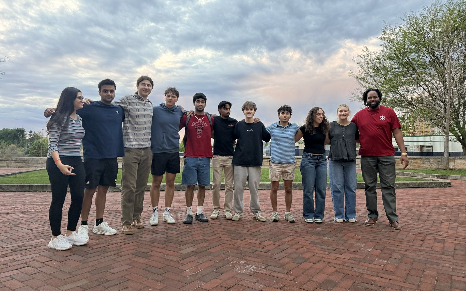
Windpack started in August 2025 with ten people and no turbine. We split into a mechanical team and an electrical team because that was the only way ten people could work in parallel, taught ourselves QBlade, and read the reports of the 2025 winners. The design report went in on April 23, 2026. Competition was May 13 to 16 at Penn State.
What we built, from that report:
- An A18 airfoil picked in QBlade for its lift to drag ratio, exported to SolidWorks. Blades printed in PLA first, which was too brittle, then in ABS.
- Each blade slid over a 6 mm shaft and was held by one M3 set screw. That was the whole root.
- Pitch by a helicopter style swash plate first, which was not stiff enough for three blades, then bevel gears inside a 40 mm hub driven by a 499:1 gearmotor. Its stall torque was about 58 times the 0.052 N·m the three blades push back with at 14 m/s.
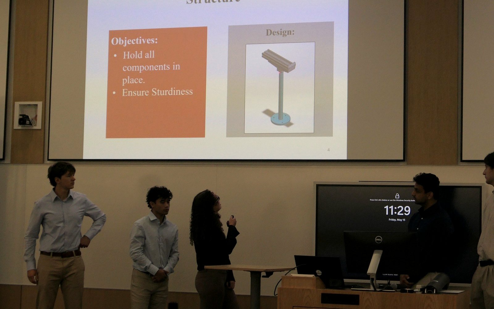
- A carbon steel tower TIG welded to a steel base disc, with the nacelle on an aluminum rail so the generator and the pitch housing could slide for balance. First bending mode estimated at 61.2 Hz by a lumped mass method, above the 58 Hz of 3,500 RPM.
- A D6374 brushless motor run backwards as the generator, 7 pole pairs, about 1 V per 150 RPM. A three phase short circuit brake, after a single phase brake shook the drivetrain, wired so it needs a constant HIGH signal to stay off: lose the controller and the rotor stops by itself. A donated solar MPPT into a 5 Ω, 250 W resistor. An Arduino Uno reading an INA226 over I2C behind optocouplers.
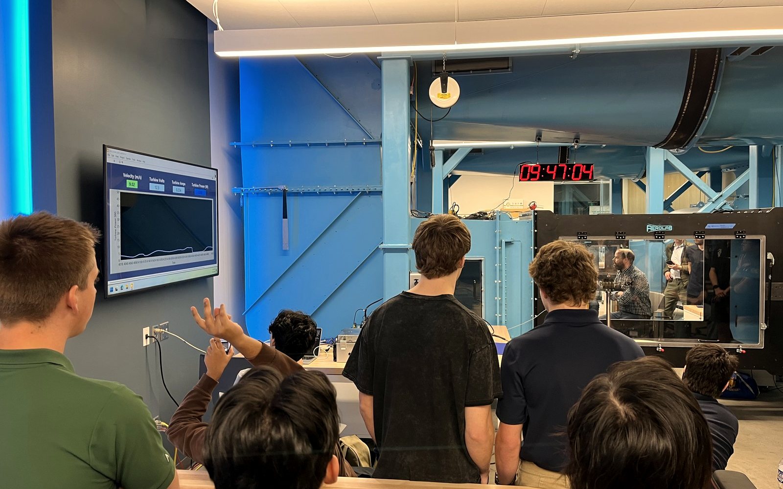
Then the tunnel. We had one practice slot. The rotor vibrated badly on spin up, so we hit the kill switch rather than lose the printed hub. The cause was rotor eccentricity: printed parts that did not line up, from small oversights in the CAD. At the event the turbine did not pass technical inspection, so no scored tunnel task was run. Sixth of ten in the East region came from the design report, the project development report, and the two presentations. The composite blades on our slides, glass fiber in epoxy laid up in a printed mold, were a bench trade study on our dynamometer. They never flew.
What broke
Printed hub and holders that did not share an axis. The eccentricity is what shook the machine in the tunnel.
Came off the shaft. One set screw into plastic is the interface every team we later benchmarked had also failed at.
Swash plates could not hold at speed. The bevel gear box that replaced them was correct in CAD and could not be assembled in the order the parts needed.
Slip ring set screws slipped, so the shaft outran the slip ring and wound the wiring around itself. Friction everywhere along the shaft.
Traces melted as the board heated. It dropped the voltage but never grounded it fully.
An inductor that saturated too soon, switching losses, and core material that cost real efficiency.
The base holes came back threaded when they should not have been. A drawing problem, redrilled in a minute.
The fine print
The judges' written advice on the turbine was two lines: improve lift over drag, and fix the blade root. The project development side did well on the report, the delivery and the financial section, and was marked down on permitting. Earlier versions of this page, and our fall kickoff slides, said the turbine survived every run at competition. It did not run. The tech inspection write up we submitted on May 1 said the turbine was in final assembly with the fit checks pending, and that is where it still was at the event.
03The retro said process, not parts
What I was thinking: Almost every item is a process problem rather than a technical one. Nobody wrote "the blades were wrong."
We photographed the four whiteboards from the end of season retro and typed them up. Deadlines had lived in nobody's calendar. The report was finished late. Decisions were made once instead of converged on. No part had a history. Sub teams did not talk to each other. The turbine was downstream of all of that.
Three answers. A gated sequence: requirements, a high level design with faculty sign off, a low level design with manufacturing sign off, then a first prototype in the fall and a second in the spring. One source of truth, a Notion workspace, so the club's memory stops living in my inbox; if something is decided in Slack and not written down, it did not happen. And a decision log that records what we considered and discarded, and why, so the next class does not relearn it.
Then the advisor check in that changed the plan. The lab's fan wall is for research, so no unofficial testing, and the large tunnel is good for one or two supervised runs a year. If we cannot iterate on someone else's equipment, the rigs we own are the iteration loop. The rotor test stand and the generator dynamometer moved onto the critical path.
04Start from the rules, then from the physics
What I was thinking: A design pipeline that only runs forward once is not a design pipeline.
Every requirement on the year two turbine traces to a rule section or to our own analysis, with a verification method and a status. The ones that drive the mechanical design:
| ID | Requirement | Source | Verify |
|---|---|---|---|
| R-01 | Rotor and non rotor parts fit in a 45 cm cube at zero yaw | Rules 3.2.2 | Inspection |
| R-07 | Withstand continuous 13 m/s wind at sea level | Rules 3.2.1 | Analysis, test |
| R-10 | Shut down to about 10% RPM within 10 s on E stop and on PCC disconnect, and stay there | Rules 3.1.4 | Test |
| R-11 | Restart automatically within 10 s, at any wind above 5 m/s | Rules 3.1.4 | Test |
| R-13 | Hold the 10 m/s power in one bin from 11 to 13 m/s | Rules 3.1.4 | Test |
| R-14 | Install in 5 min or less, commission in 5 min or less | Rules 3.2.10 | Demonstration |
| R-15 | No team built design, part or code from a past cycle | Rules 3.2.9 | Inspection |
| D-01 | Size every rotating part to the 13 m/s runaway at a safety factor of 2.0 or more | Root analysis | Analysis, test |
| D-02 | The pitch drive moves the blades through the 45° twisting moment peak at runaway speed, or shuts down toward stall where the moment helps | Root analysis | Analysis, test |
| D-04 | Blade masses matched to 0.1 g | Root analysis | Inspection |
| D-07 | Printed fits meet a clearance spec set from coupon prints before any production print | Year one | Test |
| D-08 | Overspeed spin test to 5,000 RPM before the tunnel | Root analysis | Test |
The physics starts from four lines. Power in the wind the rotor captures, the rotor speed a tip speed ratio implies, the torque that leaves, and the thrust that pushes back:
P = ½ ρ A Cp v³, ω = λ v / R, Q = P / ω, T = ½ ρ A CT v²
With a 225 mm tip radius, a Cp of 0.35 and a design tip speed ratio of 4, all placeholders until the final QBlade blade is set, the rotor makes about 34 W at 10 m/s, at about 1,700 RPM and 192 N·mm of torque. That is the operating point.
The case nobody had written down is runaway. Lose the load, the E stop or the pitch, and the rotor accelerates until the blades make no torque, at roughly twice the design tip speed ratio. At 13 m/s that is 520 rad/s, about 4,970 RPM, which matches what Cal Poly and Cal Maritime measured on their turbines. Try it:
1,698RPM
rotor speed
69N
outward pull on each blade
34.1W
shaft power
192N·mm
shaft torque
Under load the rotor runs at a tip speed ratio of 4. Each blade is holding back about 7 kg of pull.
Placeholders from the blade root analysis: 225 mm tip radius, Cp 0.35, tip speed ratio 4 under load and 9 at runaway, 22 g blades with their mass centered at 99 mm, sea level air. Above 10 m/s the controller holds the 10 m/s power. They change when the QBlade blade is final.
The operating point, bin by bin
| Wind | Shaft power | Rotor speed | Torque | Thrust |
|---|---|---|---|---|
| 5 m/s | 4.3 W | 849 RPM | 48 N·mm | 2.2 N |
| 6 m/s | 7.4 W | 1,019 RPM | 69 N·mm | 3.1 N |
| 7 m/s | 11.7 W | 1,188 RPM | 94 N·mm | 4.2 N |
| 8 m/s | 17.5 W | 1,358 RPM | 123 N·mm | 5.5 N |
| 9 m/s | 24.9 W | 1,528 RPM | 155 N·mm | 7.0 N |
| 10 m/s | 34.1 W | 1,698 RPM | 192 N·mm | 8.7 N |
| 11 to 13 m/s | 34.1 W held | about 1,700 RPM | 192 N·mm | 10.5 to 14.7 N |
| 13 m/s runaway | 0 | about 4,970 RPM | 0 | 30 N design |
Thrust uses ideal momentum theory, CT of 0.89 under load and 1.2 at runaway, and the design value of 30 N is the margin Cal Poly used for model error. Air density is 1.225 kg/m³; State College sits at about 1.18, so this is conservative.
05The root: size it for the pull, not the bend
What I was thinking: Actually! the hub's lip will be load bearing... hold on let me get back to you on that.
At runaway each 22 g blade pulls outward with F = m ω² rcg = 593 N, about sixty kilograms, and that pull grows with the square of speed. The flapwise bending moment at the root, from a conservative 30 N of rotor thrust shared by three blades, is 1.22 N·m. The pull is the design load by a wide margin, and it was the load our year one root had never been checked against.
Before sizing anything I read the four public design reports that describe their root joint in enough detail to compare. They all run 45 cm rotors, so their loads scale straight to ours.
PLA blades in a helicopter hub. Root sized for bending only at a safety factor of 1.25, centrifugal never checked. Measured 13 W at 10 m/s against 34 W predicted.
PLA bonded to a titanium and aluminum spar. Designed to 1.8 kN of centrifugal at 6,300 RPM, ran 4,500 RPM at 22 m/s without yielding. The weak point was the plastic around the fastener. Closest to our concept.
Servo and four printed miter gears. The thrust bearing alone did not take side load, the printed gears meshed poorly and could not feather at high wind.
Blades broke from speed and from handling. A 6 mm metal stub out of the root with a cross fastener was their fix.
Six things fell out. Design for runaway, not for power. Centrifugal dominates, so every gram near the tip costs root load. The plastic interface fails, the metal does not, so load has to enter the plastic over an area, not through a point fastener. Separate the load paths: thrust to a thrust bearing, bending to a radial pair, pitch torque to the gear and nothing else. Backlash is a control problem, not a tolerance footnote. And spin test to overspeed before the tunnel.
So the blade is printed in a tough resin with a 4 mm pultruded carbon rod bonded inside, root to about 35 to 45% span, in a root thickened to 18 to 20% so the rod fits with a 1 mm wall. The diameter came from σ = 32M / πd³ at 1.22 N·m:
| Rod | Stress | Safety factor | Share of root stiffness | Airfoil thickness needed |
|---|---|---|---|---|
| 3 mm | 458 MPa | 2.2 | 36% | 5.0 mm |
| 4 mm | 193 MPa | 5.2 | 64% | 6.0 mm |
| 5 mm | 99 MPa | 10.1 | 82% | 7.0 mm |
| 6 mm | 57 MPa | 17.5 | 91% | 8.0 mm |
Three millimeters meets the safety factor with no margin. Five does not fit a root that is only about 7 mm thick. The rod is not there for static strength: the resin alone would see 8.7 MPa at the root, which passes a 40 MPa static check and fails a 12 MPa fatigue one, and the tower shadow loads the root once per blade pass for the life of the machine. The rod is for fatigue, stiffness, and a clean load path into metal.
Holding the blade on costs a bond length, L = SF F / (τ π d). Epoxy into the resin bore at 5 MPa needs 19 mm, so it gets 25. Epoxy onto the abraded rod inside a steel sleeve at 15 MPa needs 6 mm, so it gets 12. A set screw on bare carbon crushes the rod at about 150 N and was rejected. From there the pull goes blade, bond, rod, bond, sleeve, sleeve flange, thrust bearing, housing lip. The lip is the piece I had forgotten was load bearing.
The thirteen weaknesses, and the fix for each
| Weakness in the first concept | Fix |
|---|---|
| A 40 mm hub plus an 8 in blade is a 48.6 cm rotor, over the 45 cm cube | Hub exit at 32 mm, 193 mm blade (later cut again to 183 mm on a 40 mm hub in the CDR, pending the CAD check) |
| One rod diameter through the whole blade; the tip is 2 mm thick | Rod to 35 to 45% span, thickened root, tapered bore at the rod end |
| Nothing retains the blade on the rod against 593 N | 25 mm epoxy bond plus a steel sleeve |
| A collar clamping bare carbon | Bonded steel sleeve with an integral flange |
| Gear held by friction, so pitch can slip silently | Flat on the sleeve spigot plus a set screw; the flange carries the axial load |
| No bearings in the blade grip, so thrust runs through the gear mesh | One thrust and two radial bearings per blade |
| Three equal miter gears collide around one central gear | 30:20 bevel set |
| Resin softens at 53 to 70 °C | A tougher resin; keep blades out of hot cars |
| Resin and carbon expand differently, about 91 against 0 µm per m·°C | Toughened epoxy, consistent cure temperature |
| Liquid resin trapped in the printed bore; cure shrink | Drain hole, wash the bore, ream after cure |
| Blade length against the printer's build height | Confirm the lab printer; print angled |
| Blade to blade mass mismatch; 1 g at 99 mm is about 27 N rotating at runaway | Weigh and match to 0.1 g, balance on the hub |
| Pitch drive sized without the twisting moment | Actuator delivers at least 1.3 N·m at the central gear |
06The hub: argue about it on a table
What I was thinking: I'm making a scaled up solidworks model and tryna get it printed tonight, so we can look at it in-person to analyze.
Four hub decisions, each with the number that made it.
Ball bearings, not bushings. Friction torque is μ F r. Under 593 N a thrust ball bearing adds 11 N·mm to the pitch torque; a bronze bushing adds 534. Bushings would make the pitch drive 5.7 times stronger, 2.37 N·m against 0.42 at the three blade gears, and they stick and slip, which shows up as pitch hunting in the rated power task. On the drive shaft a bushing would eat 11% of the rotor's torque at 5 m/s, which is where cut in is decided.
Keep the tip, accept the hub. Power per unit span grows with radius, so the fraction lost to a hub of radius rh is about (rh/R)². Growing the hub exit from 22 to 32 mm to fit the bearings costs one percent of available power. The tip radius is what matters, and the cube fixes it at 225 mm.
Bevel gears, not miter gears. Three equal 1:1 gears around one central gear sit √3 Rc apart, which is 1.73 of a blade gear radius, less than the 2 they need. They hit. A 30:20 set clears by 2 mm at module 0.5. Lewis bending on the teeth gives 64 MPa at twice the pitch torque, so the gears are steel: tough resin is good for about 12 MPa and printed teeth creep, which is backlash.
Machine the housing. The lip that carries the pull sees 15.8 MPa of shear at twice the load. In 6061 aluminum that is a safety factor of 10; in printed PLA it is 1.9. So the real hub is one piece of aluminum, bored from both ends on the shop's mill.
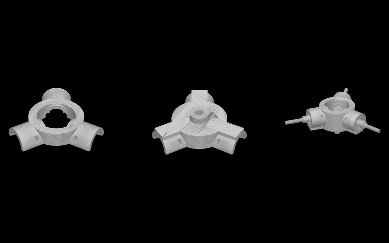
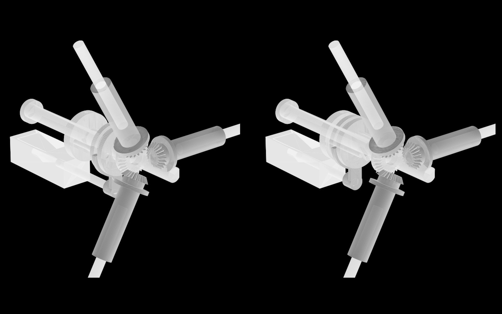
Then the part I think mattered most. I wrote the hub as a script, printed it at three times scale that night with color coded placeholders for the bearings, thrust washers, spacers and circlips, and left it in the storage room so the pitch sub team could take it apart. Four days later the drive was rebuilt as the helix Penn State uses: a nut that slides on the shaft, spins a lead screw keyed into the central gear, and pitches all three blades. Thirty millimeters of stroke gives 108 degrees of pitch at model scale, and the actuator only ever pushes along the shaft axis, which is what gets around the swash plate buckling that cost us a year ago.
The fine print
Bearing stack per arm, inboard to outboard: the gear's back face to 10 mm, the sleeve flange 10 to 11.5, an F8-16M thrust bearing 11.5 to 16.5, the housing lip 16.5 to 18, a 688ZZ 18 to 23, a 3 mm outer ring spacer, a second 688ZZ 26 to 31, and a 16 mm internal circlip at 31 to 32. Radial load per bearing with the pair 8 mm apart is 163 N against a 710 N static rating. The thrust bearing is rated about 4.9 kN against 1,190 N, twice the pull. The gear module trade: module 0.5 steel at 64 MPa exits at 32 mm; module 0.8 brass at 15 MPa exits at 36.5 mm and costs 4.5 mm of blade, about 0.6% of power. The printed model's gear teeth are approximate; the real set is a catalog part. The nut rides in a groove in the model; the real one needs a bearing there.
07The actuator question nobody had run
What I was thinking: Starting up was only a problem last competition for us because we had SOOOO much friction in our driveshaft. If we make it spin as smooth as a gust of wind, I don't see cut-in speed being a problem.
The team's first draft carried Penn State's actuator, a 22 N linear actuator, because Penn State's worked. Nobody had run the number it has to beat. A spinning blade wants to twist toward flat pitch so its mass lies in the rotor plane. That centrifugal twisting moment is ½ Jc ω² sin 2θ, so it peaks at 45 degrees of pitch, which is exactly the angle a feathering blade has to pass through.
Through the helix and the gears, that comes to about 10 N at the nut for a shutdown that starts at 1,700 RPM, and 13 to 23 N once helix friction is in. At a 13 m/s runaway it is 70 N ideal and 90 to 160 N with friction. No version of that actuator delivers the second number. So the design has a decision in it that nothing downstream can skip:
- Feather, turning the blades edge on against the twisting moment, and buy the force: a 200 N actuator of the same family, or a 21.5 kg·cm servo on a fork, the way a helicopter tail rotor slider works.
- Pitch to stall, where the twisting moment helps instead of fights, and keep the light actuator, if QBlade shows the stall angle takes the rotor below 10% RPM everywhere from 5 to 13 m/s. Penn State shut down this way.
There is also a race. When the organizers disconnect the load, the rotor starts toward runaway while the nut is still moving, and the force it needs rises with ω². Three ways to win: an actuator that can feather at runaway speed, shutting down toward stall, or a brake resistor on the turbine side that holds the rotor while the blades move.
| Option | Max force | Back drive, unpowered | 10° to 90° at 20 N | Feathers at runaway |
|---|---|---|---|---|
| L12 50:1, the baseline, 40 g | 22 N | 12 N | 1.8 s | No |
| L12 100:1 | 42 N | 22 N | 2.4 s | No |
| L12 210:1 | 80 N | 45 N | 4.0 s | No |
| L16 63:1, 56 g | 100 N | 46 N | 1.3 s | Low friction only |
| L16 150:1 | 200 N | 102 N | 2.9 s | Yes |
| Digital servo, 21.5 kg·cm, fork and 15 mm arm | 141 N stall | Gear train, open | about 0.3 s | Yes, to μ of about 0.25 |
Open at build freeze, owned by the pitch lead with the controls lead: feather or stall, the gear ratio and pitch range, and the QBlade check that stall actually reaches 10% RPM. Until a printed helix exists, the friction coefficient is a guess, which is why the force ranges are so wide. The first thing the bench test does is push on a printed helix with a scale and get a real number.
08Four bearings on one shaft is three too many
What I was thinking: Instead of it just saying, "decided to pick to use...", it could be, "We calculated that our moment on the driveshaft from the blades to be X, and the RPM to be Y, and with these bearing our driveshaft loss due to friction would be Z%."
The drivetrain is direct drive: hub, shaft, generator. The proposed generator is an outrunner with its own two bearings, and the shaft sits in two more. Two bearings define an axis. If the other two are not on it, and printed housings cannot hold four bearings concentric, the shaft bends to make up the difference. The numbers for a 6 mm aluminum shaft: a 0.1 mm offset across a 60 mm span forces about 100 N into the bearings and 69 MPa of bending that reverses every revolution, against a fatigue strength near 96 MPa for 6061-T6. That is the year one misalignment, written as a stress.
So, in order of preference: a flexible coupling between the shaft and a stub on the generator, a floating generator held only against rotation, or the generator's bearings as the rear support with a single bearing up front. Then one main bearing fixed and one free to slide, so thermal growth and the actuator's reaction have somewhere to go.
The shaft itself is small for the job: 192 N·mm of torque is 4.5 MPa in a 6 mm steel shaft. What sizes it is imbalance. A gram of mass at 99 mm makes about 27 N of rotating force at runaway, fully reversed every turn. At 0.5 g the Goodman fatigue safety factor is 2.7; at 1 g it is 1.7. That is why blades get weighed and matched to a tenth of a gram, and why the first critical speed, 16,600 RPM, about 3.3 times runaway, is worth a line in the document.
The draft also said "full ceramic bearings" with no reason attached. The standard I asked the team to write to is the one in the thought bubble: the load, the speed, and what the choice costs. The review that came back asked the same question in its own words.
Where 34 W of shaft power can go before the meter
PPCC = ½ρAv³ × Cp × ηmech × ηgen × ηelec − Paux. Each line is a loss and a way to measure it, so a gap between predicted and measured power can be traced to a stage instead of argued about.
| Stage | Loss | How it gets measured |
|---|---|---|
| Aero | Betz limit, 0.593; profile drag at small chords and low Reynolds number; tip and root loss; wake rotation; off design pitch across the bins; backlash; layer lines | QBlade with polars at the real Reynolds number, then the rotor test stand, sanded against as printed |
| Mechanical | Main bearing friction, misalignment preload, the pitch nut bearing turning at shaft speed under the actuator's load, windage from the rotating generator shell | Spin down tests, with and without the actuator loaded; runout at the generator |
| Generator | Copper, about 0.19 W at rated torque; iron loss and cogging at 280 to 570 Hz electrical, unpublished | No load loss against RPM and a static cogging torque measurement on the dynamometer |
| Electrical | Rectifier drop at 8.5 V line to line peak at 5 m/s; converter switching; cable resistance; the controller and actuator's own draw | Bench efficiency, four wire measurement, supply current per mode (the electrical review's section) |
The cautionary benchmark is Penn State's 2026 report: 34 W simulated at maximum Cp, about 13 W measured at 10 m/s. Closing that kind of gap is what the budget is for.
09The generator, and two questions nobody had asked
What I was thinking: I feel like Penn State would definitely flag this fly wheel as an energy storage element.
The proposed generator is an off the shelf robotics outrunner: 100 RPM per volt, 20 pole pairs, 840 grams. At rated turbine torque it draws about 2.3 A, roughly 6% of its 40 A continuous rating, so it carries the mass, inertia and iron of a much larger machine, and that inertia has to be stopped within 10 seconds. Open circuit at runaway is 49.7 V line to line, over the 48 V limit at the PCC, so voltage regulation is not optional and keeping the rotor out of runaway protects the meter as well as the blades. Its cogging torque is not published, and cogging is what decides whether the rotor starts at 5 m/s, in the bins that carry the heaviest weights. Those are the three things the generator's own trade study has to answer before it is ordered.
Two assumptions came with us from year one, and the handbook rule is that both get an answer in the decision log either way. First, is a three phase generator actually required by the rules, or did we inherit it. Second, the flywheel. The engineering director proposed a clutched flywheel to carry the rotor between tunnel runs. I looked up the rule instead: energy storage elements may not store bulk energy on the turbine side of the PCC, and a flywheel is bulk energy storage with a shaft on it. Vetoed. Our cut in problem in year one was never energy. It was friction.
10Reviewed, and what came back
What I was thinking: We should try and make this into comments into our CDR, resolve them, and then call that revision b.
On Oct 12 I folded the sub teams' drafts into one Critical Design Review document, WP-CDR-001, with the structure a design review needs: 18 rule requirements and 9 derived ones with verification methods, load cases and a safety factor table, an interface list, a mass budget and a loss budget, 14 tests, 17 risks, and 24 open items with owners and need by dates. Every subsystem carries a maturity label, concept, rough CAD, or proposed, so nobody mistakes a drawing for a decision. Reviewers tag comments MAJOR, MINOR, or Q and cite the requirement, risk or test ID. I sent it out for review on the 13th.
The comments came back on the 17th, and the headline was fair: it reads like a preliminary design review, not a critical one. Shaft alloy, bearing size, coupling, tower, hub body and shutdown strategy were all still open against a Nov 17 build, and the build freeze date was itself TBD. Five items were marked major, and each one has an answer now:
- Shaft material. Precision ground 6 mm steel shafting instead of aluminum. It is cheap, the tolerance is real, set screws and collars do not chew it, and it is stiffer against the critical speed with 840 g hanging on it.
- The ceramic bearings. Full ceramic carries lower load ratings, costs more, and hates misalignment and shock, which is our best documented failure mode. Plain shielded steel deep groove bearings unless a reason appears.
- Overconstraint. Agreed with the ranking: a beam coupling first. Do not ask printed housings to hold four bearings on one axis.
- Feather or stall. Everything downstream hangs on it, so it gets decided first, even provisionally.
- Set screws into prints at 5,000 RPM. No. Heat set inserts at a minimum, clamps where possible, and the same for anything structural threaded into a print.
The printed part advice went straight into the test plan: print the fit coupons in the same orientation as the real parts, because a bore printed vertically is not the same bore printed flat; measure before and after post cure; ream every bearing seat on purpose instead of as a backup; and run the rod pull out test before designing around 25 mm of bond, because the epoxy to resin shear strength is the least trusted number in the whole document. Build freeze was set for Oct 23, with the off the shelf parts order ready to send the same day.
11Test before the tunnel
What I was thinking: Blades were our most common failure last season, so the stand tests them to failure before competition, not at it.
Lab time is one or two supervised runs a year, so everything that can be learned on a bench is learned on a bench first.
| ID | Test | Pass | Before |
|---|---|---|---|
| T-01 | Printed fit coupons, measured after post cure | A fit spec | Any production print |
| T-02 | Blade mass and center of mass match | Within 0.1 g | Spin test |
| T-03 | Root static bend, point load at half span | No failure at 2.6 N·m, twice the design moment | Spin test |
| T-04 | Rod pull out, bonded in resin and in the sleeve | 1,170 N or more | Spin test |
| T-05 | Pitch bench: range, pitch against actuator position, backlash, holding under torque, helix friction | Moves and holds through the 45° peak | Spin test |
| T-06 | Drivetrain alignment: runout at the generator, spin down time | Set from the datum scheme | Generator test |
| T-07 | Generator: back EMF, cogging torque, no load loss against RPM, efficiency | A data set for the electrical review | Dec 21 |
| T-08 | Overspeed spin to 5,000 RPM behind half inch polycarbonate | No damage | Tunnel |
| T-09 | Rotor test stand: thrust and RPM against wind speed | Compared to QBlade | Tunnel |
| T-11 | Envelope: 45 cm cube gauge, 15.8 cm cylinder, a mock stud plate | Passes the inspection sheet | Tunnel |
| T-12 | Timed install and commissioning | 5 minutes each | Competition |
Three rigs make that possible. The blade dynamometer, which I pulled a three person team together to build after year one: a motor spins a blade to 2,500 RPM against a load cell and an RPM pickup on an ESP32, with the frame and motor mounts checked in ANSYS for vibration and in SolidWorks FEA so the stand's own shaking does not end up in the torque and thrust numbers. It is where the composite layups were tested against the printed blades, and it is the rig for the overspeed spin. The rotor test stand, a low friction shaft on a sliding carriage pressing a load cell, reads free spin RPM and thrust so two blade designs can be compared in an afternoon. And the generator dynamometer: a drill spins the generator against an adjustable load while it sits in a pivoting cradle with a torque arm resting on a scale, which gets torque out of cheap parts instead of a sensor.
12The other half, and the program
What I was thinking: Deliverables and timelines make people show up. Vague asks get vague results.
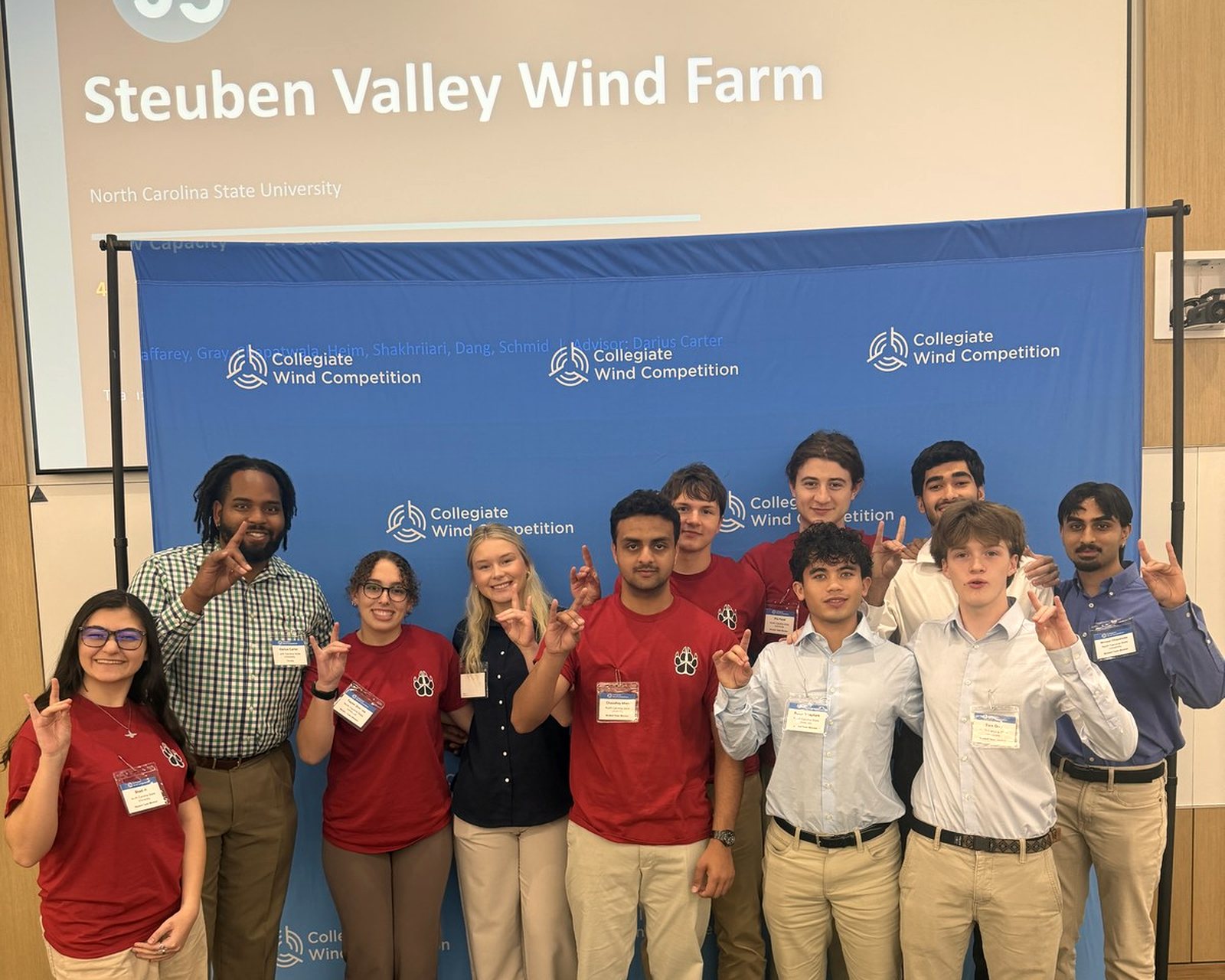
Half the competition is not a turbine. The project development contest asks for a wind farm: a site, a wind resource assessment, a layout and energy yield, environmental and permitting review, supply chain and risk, a financial model, and a lease bid defended in front of a different set of judges. Ours in year one was Steuben Valley Wind Farm, and it is the half that carried us. A fourth contest scores industry partnerships, outreach and recruiting with real numbers, and it is where being organized is the whole skill. Year two gives that half its own leads, its own weekly meeting, and its own faculty reviews, staffed with statistics, economics and environmental students next to the mechanical majors.
The program around the engineering: weekly sub team working sessions, not status reports; an officer meeting for cross team blockers; a monthly all hands so the sub teams do not become separate clubs; and a design review at each gate with faculty on both halves. Two prototypes, so there is a semester to iterate between them. The department's parts funding arrived in October. There is still no cash sponsor; the pitch lead did secure a gear analysis software license by asking the vendor.
Build freeze for prototype one, off the shelf parts ordered.
Prototype one complete, before Thanksgiving.
Event application and the controlled generator video, 5 W under control.
Controlled rotor video, wind driven.
Prototype two, the test program, the written reports, and three days at the regional event hosted by Penn State.
13Where this stands, Oct 23 2026
What I was thinking: Honest maturity labels. Nothing on this page pretends to be done when it is not.
Open at build freeze
- Feather or stall, and the actuator that follows from it.
- The generator trade study, with at least two alternatives to the proposed outrunner.
- Resin choice and the lab printer's build height against a 183 mm blade.
- The hub body design around the bearing seats.
- Tower height, pending the host's tunnel centerline.
Next
- Coupon prints and the rod pull out test, this week.
- Revision C of the CDR with every reviewer comment answered and the mass properties filled in.
- The electrical review, WP-CDR-002, for the load, the converter and the shutdown logic.
- A generator spinning under control on the dynamometer before Dec 21.
Still to write
- Measured numbers: the first coupon fits, the pull out force, the cogging torque, the first spin down.
- The overspeed spin test, and what the blades look like afterwards.
- The first tunnel run of prototype one, whichever way it goes.
- Shop and bench photos. Year one was photographed at competition and almost nowhere else, which is its own lesson.